| Scientific Equipments & Products |
|
|
| Forces Apparatus: |
| Forces Apparatus Manufacturers - Funicular Polygon and Forces Apparatus, Shearing Force Apparatus, Bending Moment Apparatus and Work done by a Variable Force (Tangential Effort) |
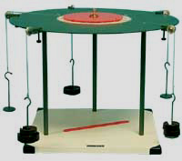
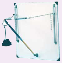
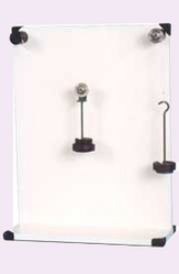
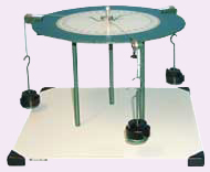
 Funicular Polygon and Forces Apparatus Funicular Polygon and Forces Apparatus
Low cost, effective teaching
Self-contained, bench mounted
Direct measurement of forces
Adjustable lines of action of forces
Practical verification of triangle of forces, polygon of forces and link polygon
Demonstrates equilibrium of forces at a point, applied to various points round a
disc or acting on a rectangular lamina
Concurrent & Non-concurrent coplanar forces
Three year warranty
Range of Experiments
- To resolve by experiment any suitable system of static coplanar forces which may or may not be concurrent
- To verify graphically using:
a) triangle of forces for three concurrent coplanar forces
b) polygon of forces for more than three concurrent coplanar forces
c) link polygon for three or more non-concurrent coplanar forces
- To investigate (c) for either a disc or a rectanglar shape
- To compare the accuracy of the experiment by comparing the experimental and graphical results
Description
This
apparatus is a more comprehensive and versatile version of the HFC2. A
simple but elegant demonstration of the conditions of equilibrium for
three or more coplanar forces acting either at a point, on a circular
disc or on a rectangular shape. Up to five loads can be applied to the
chosen shape by setting up pulleys at various angular positions. The
lines of action of the forces are recorded by drawing along the weighted
cords onto a piece of paper attached to the pulley table. A range of
experiments is possible, investigating concurrent and non concurrent
coplanar forces acting on simple shapes, comparing the experimental
values with the relevant polygons of force.
This equipment is
part of a range designed to both demonstrate and experimentally confirm
basic engineering principles. Great care has been given to each item so
as to provide wide experimental scope without unduly complicating or
compromising the design. Each piece of apparatus is self-contained and
compact. Setting up time is minimal, and all measurements are made with
the simplest possible instrumentation, so that the student involvement
is purely with the engineering principles being taught. A complete
instruction manual is provided describing the apparatus, its
application, experimental procedure and typical test results.
|
 |
| |
|
| |
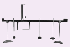
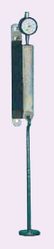
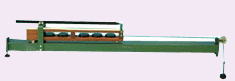
Shearing Force Apparatus
Features
- Low cost, effective teaching
- Self-contained
- Bench mounted
- Direct measurement of Shear Force
- Loads and supports can be placed in
any position
- Visual practical verification of the
concept of Shear Force
- Allows investigation of stability and
influence lines
- Reinforces concept of equilibrium of vertical forces & moments
- Three year warranty
Range of Experiments
- To comprehend the action of shear in a beam
- To measure the shearing force at a section of a loaded beam, and to compare with a theoretical estimate
- To study the definition of an influence line for shear force
Description
A
length of material supported horizontally and carrying vertical loads
is called a beam. The loading causes bending and transverse shearing.
The loads and reactions are the 'external' forces acting on the beam.
They must be in equilibrium. However, the strength of the beam depends
on 'internal' forces. This experiment demonstrates the nature of these
internal forces and their dependence on the external system of forces.
The
experimental beam is in two parts, joined by a pair of ball bearing
rollers running in flat vertical tracks. To develop the internal beam
forces at the section an underslung tension spring is used to resist the
bending moment, while an overhung spring balance provides the vertical
shearing force. Due to the mechanical arrangement, there must always be a
net downward load on the longer side of the split beam.
The beam
is simply supported on end bearings and several weight hangers can be
attached at any position on either side of the joint. A hinged metal
strip is available to simulate the loading pattern of a panelled girder
for a more advanced experiment on influence lines.
This equipment
is part of a range designed to both demonstrate and experimentally
confirm basic engineering principles. Great care has been given to each
item so as to provide wide experimental scope without unduly
complicating or compromising the design. Each piece of apparatus is
self-contained and compact. Setting up time is minimal, and all
measurements are made with the simplest possible instrumentation, so
that the student involvement is purely with the engineering principles
being taught. A complete instruction manual is provided describing the
apparatus, its application, experimental procedure and typical test
results. |
 |
| |
|
| |
|
|
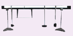
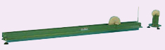
Bending Moment Apparatus
Features
- Low cost, effective teaching
- Self-contained
- Bench mounted
- Experimental determination of bending
moment at a beam section
- Loads and supports can be placed in
any position
- Visual vertification of the nature of
bending moment
- Allows investigation of stability and
influence lines
- Reinforces concept of equilibrium of
vertical forces and moments
- Three year warrant
Range of Experiments
- To comprehend the action of moment of resistance in a beam
- To measure the bending moment at a section of a loaded beam and to compare with a theoretical estimate
- To study the definition of an influence line for bending moment
Description
A
length of material supported horizontally and carrying vertical loads
is called a beam. The loading causes bending and transverse shearing.
The loads and reactions are the 'external' forces acting on the beam.
They must be in equilibrium. However, the strength of the beam depends
on 'internal' forces or moments. This experiment demonstrates the nature
of these internal forces and their dependence on the external system of
forces.
The experimental beam is in two parts, joined together
by a pair of low friction ball bearings. An underslung spring balance
provides a resisting moment, and also allows the section bending moment
to be measured. A hinged metal strip to simulate the loading pattern of
panelled girder for a more advanced experiment on influence lines is
available.
The beam is simply supported on end bearings and
several weight hangers can be attached at any position on either side of
the hinge.
This equipment is part of a range designed to both
demonstrate and experimentally confirm basic engineering principles.
Great care has been given to each item so as to provide wide
experimental scope without unduly complicating or compromising the
design. Each piece of apparatus is self-contained and compact. Setting
up time is minimal, and all measurements are made with the simplest
possible instrumentation, so that the student involvement is purely with
the engineering principles being taught. A complete instruction manual
is provided describing the apparatus, its application, experimental
procedure and typical test results. |
 |
| |
|
| |
|
|
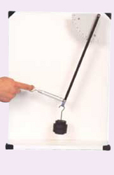
Work done by a Variable Force (Tangential Effort)
Features
- Low cost, effective teaching
- Self-contained
- Bench mounted
- Reinforces concepts of work and energy
- Direct reading of tangential effort
- Three year warranty
Range of Experiments
- To
obtain the experimental relationship between effort and distance moved
by effort, and to compare with a theoretical prediction
- To show that the work done is the area under a graph of load against distance moved
Description
This
experiment is designed to reinforce the general principle that the work
done, particularly by a variable force, can be determined simply by
measuring the area under the graph of force and distance moved. The
equipment is deliberately simple so that concepts are readily grasped.
It is a companion experiment to HFC6, which is concerned with the work
done by available vertical force.
A pivoted arm carrying a weight
at its end is restrained by a spring balance at right angles to the
arm. The angular position of the arm is indicated by a protractor scale.
The
effort is the force needed to hold the weighted arm at a particular
angle. This can be repeated for several different weights.
This
equipment is part of a range designed to both demonstrate and
experimentally confirm basic engineering principles. Great care has been
given to each item so as to provide wide experimental scope without
unduly complicating or compromising the design. Each piece of apparatus
is self-contained and compact. Setting up time is minimal, and all
measurements are made with the simplest possible instrumentation, so
that the student involvement is purely with the engineering principles
being taught. A complete instruction manual is provided describing the
apparatus, its application, experimental procedure and typical test
results. |
 |
| |
|
| |
|
|
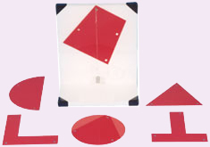
Centre of Gravity Apparatus
Features
- Low cost, effective teaching
- Self-contained
- Bench mounted
- Six different shapes
- Direct location of Centre of Gravity by drawing
- Three year warranty
Range of Experiments
- To
establish the position of the centre of gravity of several different
shapes by experiment, and to compare with values derived from
calculation or reference books
Description
The
centre of gravity of a shape of uniform thickness can easily be found by
this method. It provides a simple technique for complicated shapes, far
quicker than by using calculus for example, although not producing an
accurate answer to the handling of a yacht, the calculation of the
moments caused by the wind and water acting at the 'centre of lateral
area' of the sails and keel are still used as a starting point.
A
free standing backboard has a pin from which a selection of flat shapes
can be hung. A simple pendulum suspended from the pin enables the line
of action of the weight to be transferred to the lamina. The centre of
gravity is the position on the shape where two or more such lines
intersect.
This equipment is part of a range designed to
both demonstrate and experimentally confirm basic engineering
principles. Great care has been given to each item so as to provide wide
experimental scope without unduly complicating or compromising the
design. Each piece of apparatus is self-contained and compact. Setting
up time is minimal, and all measurements are made with the simplest
possible instrumentation, so that the student involvement is purely with
the engineering principles being taught. A complete instruction manual
is provided describing the apparatus, its application, experimental
procedure and typical test results. |
 |
| |
|
| |
|
|
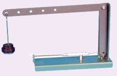
Bell Crank Lever
Features
- Low cost, effective teaching
- Self-contained
- Bench mounted
- 5 different lever ratio
- Direct readout of reaction by
spring balance
- Three year warranty
Range of Experiments
- To determine by experiment the reaction force of a bell-crank lever to an applied load
- To confirm the effect of leverage ratio
- To compare with calculation by taking moments about the pivot
Description
Lever
mechanisms of all shapes and sizes are very common parts of machines,
particularly in hand operated devices. The bell crank lever offers the
typical mechanical advantage of a lever, and in addition it turns the
line of action of the effort through 90°. In most cases the cranked
lever would be a casting with a bushed pivot at the corner. The
experimental model has been built up from plastic to simulate the real
thing.
This traditional item enables the reaction force of a 90°
bell crank to be measured by a spring balance when a load is applied at
any of five leverage ratios.
The bell crank is supported on a bushed pivot.
This
equipment is part of a range designed to both demonstrate and
experimentally confirm basic engineering principles. Great care has been
given to each item so as to provide wide experimental scope without
unduly complicating or compromising the design. Each piece of apparatus
is self-contained and compact. Setting up time is minimal, and all
measurements are made with the simplest possible instrumentation, so
that the student involvement is purely with the engineering principles
being taught. A complete instruction manual is provided describing the
apparatus, its application, experimental procedure and typical test
results. |
 |
| |
|
| |
|
|
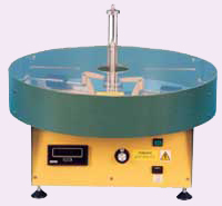
Centrifugal Force Apparatus
Features
- Low cost, effective teaching
- Self-contained
- Wall mounted
- Speed, rotating mass, and radius of
gyration independently variable
- Direct readout of centrifugal force by
spring balance
- Direct readout of rotational speed by
digital tachometer
- Fully guarded
- Three year warranty
Range of Experiments
- To verify that the centrifugal force on a rotating mass is proportional to the:-
- square of the speed
- mass
- radius of gyration
- To compare the experimental results with those calculated from theory
Description
This
apparatus is used to verify that centrifugal force varies with the
square of the speed, the rotating mass, and the radius of gyration. A
unique feature is that all three variables can be set and the
centrifugal force directly read from the spring balance. Six masses are
supplied. The unit has a built-in variable speed drive and digital
tachometer.
The equipment is fully guarded (not shown in the photograph).
This
equipment is part of a range designed to both demonstrate and
experimentally confirm basic engineering principles. Great care has been
given to each item so as to provide wide experimental scope without
unduly complicating or compromising the design. Each piece of apparatus
is self-contained and compact. Setting up time is minimal, and all
measurements are made with the simplest possible instrumentation, so
that the student involvement is purely with the engineering principles
being taught. A complete instruction manual is provided describing the
apparatus, its application, experimental procedure and typical test
results. |
 |
| |
|
| |
|
|
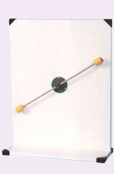
Conservation of Angular Momentum
Features
- Low cost, effective teaching
- Self-contained
- Wall mounted
- High visual impact
- Genuine "hands-on" experience
- Three year warranty
Range of Experiments
- Used
for demonstration only, no measurements are intended. Demonstrates
basic concepts of conservation of angular momentum through visual
observation
Description
Conservation of linear
momentum is well understood and often demonstrated to students. Equally
important is the conservation of angular momentum. It is not easy to do
meaningful experiments on this, but a highly visual demonstration of
almost dramatic impact is the effect of reducing the radius of a
rotating mass. This is often seen in an ice skater performing a
pirouette. First they spin round on an axis corresponding to their body,
arms outstretched. When they raise their arms above their head, the
increase in spin in considerable. Rather than go to an ice rink,
students can perform this experiments in the laboratory.
A bench
mounted vertical board has a rotating arm along which two weights can be
moved by a pull cord operated by the student or demonstrator.
The
weights are moved to the outer ends of their travel, away from the
centre of rotation. The arm is then spun rapidly by hand, and the
weights pulled towards the centre by the cord.
The resulting increase in angular velocity is considerable.
This
equipment is part of a range designed to both demonstrate and
experimentally confirm basic engineering principles. Great care has been
given to each item so as to provide wide experimental scope without
unduly complicating or compromising the design. Each piece of apparatus
is self-contained and compact. Setting up time is minimal, and all
measurements are made with the simplest possible instrumentation, so
that the student involvement is purely with the engineering principles
being taught. A complete instruction manual is provided describing the
apparatus, its application, experimental procedure and typical test
results. |
 |
| |
|
| |
|
|
Forces Apparatus
Features
- Low cost, effective teaching
- Self-contained
- Wall mounted
- Evaluation of forces in levers and slings
for lifting heavy objects
- Three year warranty
Range of Experiments
- Reactions of levers
- Forces acting at an angle
- Forces at a point
- Finding centres of gravity
Description
For
forces on levers, sling forces, equilibrium forces, etc and
particularly suitable for motor vehicle courses. All components for the
above experiments are supplied as standard. Five geometric shapes with a
simple pendulum can be supplied as an optional extra for centre of
gravity experiments.
This equipment is part of a range designed
to both demonstrate and experimentally confirm basic engineering
principles. Great care has been given to each item so as to provide wide
experimental scope without unduly complicating or compromising the
design. Each piece of apparatus is self-contained and compact. Setting
up time is minimal, and all measurements are made with the simplest
possible instrumentation, so that the student involvement is purely with
the engineering principles being taught. A complete instruction manual
is provided describing the apparatus, its application, experimental
procedure and typical test results. |
 |
| |
|
| |
|
|
Three Wire Suspension Apparatus
Features
- Low cost, effective teaching
- Self-contained
- Bench mounted
- Direct measurement of horizontal reaction
- Angle of toggle variable
- Demonstrates application of velocity
diagrams
- Three year warranty
Range of Experiments
- To study the vertical equilibrium of a two and three wire suspension system
- To examine the action of the central vertical redundant force
Description
A
free standing backboard provides supports for three tensile suspenders
that meet at a ring carrying a load hanger. Spring balances measure the
tension in each of the suspenders which are at about 30 and 45 degrees
to the central vertical one. The lengths of each suspender can be
adjusted by a threaded rod attached to the spring balance.
This
equipment is part of a range designed to both demonstrate and
experimentally confirm basic engineering principles. Great care has been
given to each item so as to provide wide experimental scope without
unduly complicating or compromising the design. Each piece of apparatus
is self-contained and compact. Setting up time is minimal, and all
measurements are made with the simplest possible instrumentation, so
that the student involvement is purely with the engineering principles
being taught. A complete instruction manual is provided describing the
apparatus, its application, experimental procedure and typical test
results. |
 |
| |
|
| |
|
|
Toggle Joint Apparatus
Features
- Low cost, effective teaching
- Self-contained
- Bench mounted
- Direct measurement of horizontal reaction
- Angle of toggle variable
- Demonstrates application of
velocity diagrams
- Three year warranty
Range of Experiments
- To determine the experimental horizontal reaction due to loading
- To compare with theoretical predictions, such as the velocity diagram technique
- To assess the effect of the toggle angle
Description
This
apparatus is designed to evaluate forces within a toggle mechanism.
Load is applied to the two pairs of links by a hanger suspended from
their connecting pivot. One end of the links is pivoted to a base, and
the other end is able to move sideways on low friction ball bearing
wheels. The moving links are restrained by a horizontal spring balance,
which measures the horizontal reaction directly. The angle of the toggle
can be varied. Adjustment is provided for returning the geometry of the
loaded toggle to its original unloaded state before taking
measurements. The supporting blocks are not supplied.
There are
many ways in which the forces can be determined theoretically. The
instruction sheet provided with the apparatus takes the opportunity to
introduce the use of velocity diagrams to solve essentially static
problems by considering virtual motion. However, other techniques can be
used if desired.
This equipment is part of a range designed to
both demonstrate and experimentally confirm basic engineering
principles. Great care has been given to each item so as to provide wide
experimental scope without unduly complicating or compromising the
design. Each piece of apparatus is self-contained and compact. Setting
up time is minimal, and all measurements are made with the simplest
possible instrumentation, so that the student involvement is purely with
the engineering principles being taught. A complete instruction manual
is provided describing the apparatus, its application, experimental
procedure and typical test results. |
 |
| |
|
| |
|
|
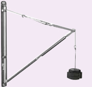
Shear Legs
- Low cost, effective teaching
- Self-contained
- Bench mounted
- Direct measurement of strut and backstay forces by spring balance
- Three year warranty
Range of Experiments
- Experimental determination of forces in shear legs
- Comparison with theoretical prediction
- To assess the effect of changing the shear leg geometry
Description
Shear
legs are often used to make temporary cranes. In this experiment the
ideas developed in experiments with several forces in one plane are
extended to three dimensions. Clarity of thought is encouraged, since
there are both compressive and tensile forces present.
The double
shear legs are mounted on rollers which run on a round bar. Compression
forces in the legs are measured with integral spring balances, and
restraint is by an adjustable tie chain. The back stay is adjustable and
is also fitted with a spring balance. Loading is by a weight hung from
the apex.
The unit is free standing on a bench top.
This
equipment is part of a range designed to both demonstrate and
experimentally confirm basic engineering principles. Great care has been
given to each item so as to provide wide experimental scope without
unduly complicating or compromising the design. Each piece of apparatus
is self-contained and compact. Setting up time is minimal, and all
measurements are made with the simplest possible instrumentation, so
that the student involvement is purely with the engineering principles
being taught. A complete instruction manual is provided describing the
apparatus, its application, experimental procedure and typical test
results. |
 |
| |
|
| |
|
|
Tension Coefficients Apparatus
Features
- Low cost, effective teaching
- Self-contained
- Wall mounted
- Direct reading of jib and tie loads using spring balances
- Demonstrates the application of tension coefficient to evaluate forces in three dimensions
Range of Experiments
- To determine experimentally forces induced in individual frame members
- To calculate the theoretical forces induced, using the method of tension coefficients
- To compare the experimental and theroretical results
- To repeat for other frame configurations
Description
The
apparatus consists of a jib restrained by two chain ties making a
triangulated three dimensional structure. The jib and both ties are
fitted with spring balances so that the internal forces can be measured.
The
bottom of the jib is pivoted to the wall mounted plate and the tie
attachment locations can be varied independently at their wall ends.
A
load is hung from the jib end, and the geometry returned to its
unloaded state using a knurled collar before taking the spring balance
readings.
This equipment is part of a range designed to both
demonstrate and experimentally confirm basic engineering principles.
Great care has been given to each item so as to provide wide
experimental scope without unduly complicating or compromising the
design. Each piece of apparatus is self-contained and compact. Setting
up time is minimal, and all measurements are made with the simplest
possible instrumentation, so that the student involvement is purely with
the engineering principles being taught. A complete instruction manual
is provided describing the apparatus, its application, experimental
procedure and typical test results. |
 |
| |
|
| |
|
|
Rubber in Shear Apparatus
Features
- Low cost, effective teaching
- Self-contained
- Wall mounted
- Range of pivot angles supplied
- Optional bearings available
- Determination of modulus of rigidity and Poissons Ratio
- Three year warranty
Range of Experiments
- To determine the variation of deflection with applied load
- To investigate the relationship between shear stress and shear strain
- To find the modulus of rigidity of the rubber block
Description
Rubber
blocks in shear force are often used on engine and in equipment
mounting to isolate vibrations. They do this by absorbing shock energy
by deforming. This deformation leads to a decrease in cross-section as
the block lengthens, an effect described by Poisson's Ratio. After this
experiment, students will understand the behaviour of a very flexible
material such as rubber. Rubber is interesting in that the lay person
regards it as an 'elastic' material. In engineering terms it is not as
'elastic' as steel and often exhibits a high degree of hysteresis.
A
rubber block 150 x 75 x 25mm is bonded to two aluminium alloy plates.
One plate is screwed to a wall, whilst the other has a shear load
applied by a loaded weight hanger. A dial gauge measures the deflection
of the block.
This equipment is part of a range designed to both
demonstrate and experimentally confirm basic engineering principles.
Great care has been given to each item so as to provide wide
experimental scope without unduly complicating or compromising the
design. Each piece of apparatus is self-contained and compact. Setting
up time is minimal, and all measurements are made with the simplest
possible instrumentation, so that the student involvement is purely with
the engineering principles being taught.
A complete instruction
manual is provided describing the apparatus, its application,
experimental procedure and typical test results. |
 |
| |
|
| |
|
|
Basic Roof Truss
Features
- Low cost, effective teaching
- Self-contained
- Bench mounted
- Truss angle can be varied
- Direct read out of strut and tie forces by spring balances
- Three year warranty
Range of Experiments
- To compare experimental values of the forces in the struts and tie of a basic roof truss with theoretical predictions
- To observe the effect of changing the tie bar length
Description
The
basic roof truss consists of two rafters or struts and a restraining
tie. Both rafters are pivoted at their apex. The other end of one of the
rafters is pivoted to a free standing base, whilst the remaining rafter
end runs on ball bearings along a track. When a load is hung from the
apex, the free end of the rafter moves sideways, restrained by a spring
balance tie.
Both rafters also include spring balances so that all internal loads can be directly measured.
Re-adjustment
of the geometry back to its original unloaded configuration is easily
made before taking measurements. The length of the tie can be varied to
change the angles of the truss.
This equipment is part of a range
designed to both demonstrate and experimentally confirm basic
engineering principles. Great care has been given to each item so as to
provide wide experimental scope without unduly complicating or
compromising the design. Each piece of apparatus is self-contained and
compact. Setting up time is minimal, and all measurements are made with
the simplest possible instrumentation, so that the student involvement
is purely with the engineering principles being taught. A complete
instruction manual is provided describing the apparatus, its
application, experimental procedure and typical test results. |
 |
| |
|
| |
|
|
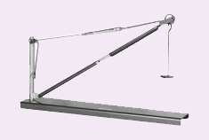
Derrick Crane
Features
- Low cost, effective teaching
- Self-contained
- Bench mounted
- Direct readout of jib and tie loads by spring balances
- Demonstrate principles of equilibrium and polygon of forces
- Three year warranty
Range of Experiments
- Determination of forces in the crane members
- Comparison with prediction by the polygon of forces
- Demonstration of equilibrium of forces
Description
This
apparatus represents the forces in a simple crane and introduces the
student to equilibrium of forces and solution by the triangle of forces.
The crane is mounted on a base designed to be stood on a level bench.
Both the jib and tie include spring balances for measuring the internal forces. A load is hung from the end of the jib.
Re-adjustment
of the crane geometry back to its original unloaded layout is possible
by a knurled adjuster on the jib and adjusting the links of the chain.
This
equipment is part of a range designed to both demonstrate and
experimentally confirm basic engineering principles. Great care has been
given to each item so as to provide wide experimental scope without
unduly complicating or compromising the design. Each piece of apparatus
is self-contained and compact. Setting up time is minimal, and all
measurements are made with the simplest possible instrumentation, so
that the student involvement is purely with the engineering principles
being taught. A complete instruction manual is provided describing the
apparatus, its application, experimental procedure and typical test
results. |
 |
| |
|
| |
|
|
Work done by a Variable Force (Vertical Effort)
Features
- Low cost, effective teaching
- Self-contained
- Bench mounted
- Reinforces concepts of work and energy
- Three year warranty
Range of Experiments
- To determine the work done by a variable effort and to compare with the work done in lifting the load
- To show that the work done by the effort is equal to the change in potential energy of the load
Description
This
experiment is designed to reinforce the general principle that the work
done, particularly by a variable force, can be determined simply by
measuring the area under the graph of force and distance moved. It forms
a comparison experiment with HFC7 which is concerned with the work done
by a variable tangential force.
The experiment is deliberately
simple so that theoretical comparisons are easily made. It forms a good
introduction to simple machines, leading to later studies on machine
performance.
The apparatus is a simple lifting mechanism with
obvious non linear characteristics. A suspension cord carrying a loaded
trolley at mid span is tensioned by passing the cord over a pulley at
one end and down to a weight hanger. As the vertical effort is
increased, the tensioned cord will move to a new equilibrium position
lifting the loaded trolley. Heights of the load and effort are measured
relative to the base.
All the pulleys are fitted with ball bearings to minimise friction effects.
This
equipment is part of a range designed to both demonstrate and
experimentally confirm basic engineering principles. Great care has been
given to each item so as to provide wide experimental scope without
unduly complicating or compromising the design. Each piece of apparatus
is self-contained and compact. Setting up time is minimal, and all
measurements are made with the simplest possible instrumentation, so
that the student involvement is purely with the engineering principles
being taught. A complete instruction manual is provided describing the
apparatus, its application, experimental procedure and typical test
results. |
 |
| |
|
| |
|
|
Simple Moments Apparatus
Features
- Low cost, effective teaching
- Self-contained
- Bench mounted
- Demonstrates concept of moment
equilibrium
- Three year warranty
Range of Experiments
- To apply a stable system of loading to a pivoted beam
- To compare with values obtained from calculation using simple moments
Description
This
equipment provides a simple easy to understand experiment on the
equilibrium of moments. Several loads can be put on the beam at various
positions. These will make the beam rotate. The student has to determine
the moment necessary to overcome this rotation and keep the beam level.
On a practical level, this principle is used in the measurement of
goods, such as in chemical balances and steelyards.
The alloy
beam is 530mm long and graduated in each direction from the central
pivot in cm. Three wire stirrups, weight hangers and a set of weights
are included.
This equipment is part of a range designed to both
demonstrate and experimentally confirm basic engineering principles.
Great care has been given to each item so as to provide wide
experimental scope without unduly complicating or compromising the
design. Each piece of apparatus is self-contained and compact. Setting
up time is minimal, and all measurements are made with the simplest
possible instrumentation, so that the student involvement is purely with
the engineering principles being taught. A complete instruction manual
is provided describing the apparatus, its application, experimental
procedure and typical test results. |
 |
| |
|
| |
|
|
Wall Jib Crane
Features
- Member forces all directly measured
- Rapidly variable configuration
- Wall mounted
- Folds flat to the wall
- Three year warranty
Range of Experiments
- Comparison of measured forces with a triangle of forces and theoretical values
- Comprehension of the action of the crane cable forces on the jib and the effect of the jib inclination
Description
Although
wall jib cranes are obsolete, the self evident confluence of the four
forces at the end of the jib illustrates the application of a triangle
of forces so clearly to a real situation that this is an invaluable
lesson.
This wall mounted self-contained jib crane has spring
balances built into its two members. After loading the member lengths
can be adjusted to their no-load lengths. The jib out-hang and the crane
cable inclination can be readily changed. An instruction sheet is
provided.
This equipment is part of a range designed to both
demonstrate and experimentally confirm basic engineering principles.
Great care has been given to each item so as to provide wide
experimental scope without unduly complicating or compromising the
design. Each piece of apparatus is self-contained and compact. Setting
up time is minimal, and all measurements are made with the simplest
possible instrumentation, so that the student involvement is purely with
the engineering principles being taught. A complete instruction manual
is provided describing the apparatus, its application, experimental
procedure and typical test results. |
 |
| |
|
| |
|
|
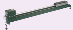
Acceleration Apparatus
Features
- Self-contained
- Bench mounted
- Novel gliding design
- Total mass of moving system can be kept constant for different acceleration masses
- Acceleration determination by spark generator and electro-sensitive paper
- Confirmation of Newton's Second Law
of Motion
- Determination of gravitational acceleration
- Three year warranty
Range of Experiments
- To show that a force causes a mass to accelerate, and that the acceleration is proportional to the force
- To compare experimental and theoretical values of forces required to accelerate a given mass
- To determine the acceleration due to gravity, g
Description
This
type of equipment has been used for many years to introduce students to
accelerated linear motion, in particular the dependence of the
acceleration on the net force causing the motion. Confirmation of
Newton's second law of motion and the determination of gravitational
acceleration are possible.
The trolley which carries five removable masses glides on two rails attached to the base.
Electro-sensitive
paper strip attached to the trolley passes through a spark generator
which produces five impulses per second, enabling the trolley
acceleration to be accurately determined.
The weights which produce the accelerating force are hung directly onto the paper strip.
All required equipment is supplied. Further rolls of electro-sensitive paper are available.
This
equipment is part of a range designed to both demonstrate and
experimentally confirm basic engineering principles. Great care has been
given to each item so as to provide wide experimental scope without
unduly complicating or compromising the design. Each piece of apparatus
is self-contained and compact. Setting up time is minimal, and all
measurements are made with the simplest possible instrumentation, so
that the student involvement is purely with the engineering principles
being taught. A complete instruction manual is provided describing the
apparatus, its application, experimental procedure and typical test
results |
 |
| |
|
| |
|
|
Fletcher's Trolley
Features
- Traditional design
- Self-contained
- Bench mounted
- Total mass of moving system can be maintained constant for different
acceleration masses
- Five trolley masses
- Acceleration determination by ink trace
- Confirmation of Newton's Second Law
of Motion
- Determination of Gravitational Acceleration
- Three year warranty
Range of Experiments
- To show that a force causes a mass to accelerate, and that the acceleration is proportional to the force
- To compare experimental and theoretical values of forces required to accelerate a given mass
- To determine the acceleration due to gravity, g
Description
This
type of equipment has been used for many years to introduce students to
accelerated linear motion, in particular the dependence of the
acceleration on the net force causing the motion. Confirmation of
Newton's second law of motion and the determination of gravitational
acceleration are possible.
This strongly built traditional
apparatus produces very accurate results. The trolley has five removable
weights. During an experiment, the total mass of the moving equipment
can be maintained constant by transferring weights from the rear of the
trolley to the load hanger.
Acceleration is measured using an
inked brush attached to a vibrating arm. This traces out an oscillatory
trace on a piece of paper fixed to the trolley.
This equipment is
part of a range designed to both demonstrate and experimentally confirm
basic engineering principles. Great care has been given to each item so
as to provide wide experimental scope without unduly complicating or
compromising the design. Each piece of apparatus is self-contained and
compact. Setting up time is minimal, and all measurements are made with
the simplest possible instrumentation, so that the student involvement
is purely with the engineering principles being taught. A complete
instruction manual is provided describing the apparatus, its
application, experimental procedure and typical test results. |
 |
| |
|
| |
|
|
Rolling Disc on Inclined Plane
Features
- Low cost, effective teaching
- Self-contained
- Bench mounted
- Measurement of moment of inertia by
rolling and oscillation
- Three year warranty
Range of Experiments
To determine and compare the moment of inertia of a disc by three methods:-
- Motion down a plane
- Oscillating pendulum
- Calculation
Description
The
moment of inertia of a rolling object is the rotary analagy of mass and
governs the rotary acceleration. It can be determined in three ways; by
rolling, oscillation or calculation. All should ideally give the same
result but the student can be introduced to differences caused by
different experimental techniques
A pair of machined rails form
an inclined track for a disc rolling on a spindle through its centre.
The inclination of the track can be readily altered by raising an end
fitted with a height bar. Two discs are supplied; the larger has a
diameter of 150mm and a thickness of 22.5mm, whilst the smaller is 100mm
by 20mm. This enables two moments of inertia to be used.
The
moments of inertia of the discs are determined from the time taken for
the disc to roll down the slope. They may also be found from a
subsidiary experiment using an oscillating pendulum in which the disc
spindles are supported on knife edge bearings and a pendulum is attached
to the shaft. The moments of inertia are estimated from the periodic
time of the assembly.
This equipment is part of a range designed
to both demonstrate and experimentally confirm basic engineering
principles. Great care has been given to each item so as to provide wide
experimental scope without unduly complicating or compromising the
design. Each piece of apparatus is self-contained and compact. Setting
up time is minimal, and all measurements are made with the simplest
possible instrumentation, so that the student involvement is purely with
the engineering principles being taught. A complete instruction manual
is provided describing the apparatus, its application, experimental
procedure and typical test results. |
 |
| |
|
| |
|
|
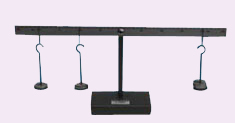
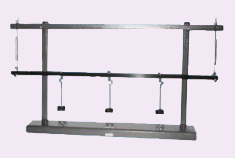
Reaction of Beams Apparatus
Features
- Low cost, effective teaching
- Self-contained
- Bench mounted
- Direct measurement of reactions by
spring balances
- Loads and supports can be placed in
any position
- Practical verification of equilibrium of
vertical force or moments
- Simply supported beams or levers can
be set up
- Three year warranty
Range of Experiments
- Experimental determination of the reaction forces in the supports of a simply supported beam under various loadings
- Measurement of loads and moments on a lever
- Comparison with calculated results and validation of the principle of equilibrium
Description
A
horizontal length of material with a vertical load system is called a
beam. It is one of the most basic engineering ways of supporting a load.
External forces such as the applied loads and the beam support
reactions have to be in equilibrium. Given a loading system, the support
reactions can be calculated from force and moment equations.
This
apparatus is designed for simple experiments and demonstrations on
simply supported beams. Two spring balances act as supports and enable
reactions to be read directly. Three movable load hangers allow loads to
be put in a number of positions.
Levers can be investigated by suspending the beam from the free standing frame, and holding down the end with a spring balance.
This
equipment is part of a range designed to both demonstrate and
experimentally confirm basic engineering principles. Great care has been
given to each item so as to provide wide experimental scope without
unduly complicating or compromising the design. Each piece of apparatus
is self-contained and compact. Setting up time is minimal, and all
measurements are made with the simplest possible instrumentation, so
that the student involvement is purely with the engineering principles
being taught. A complete instruction manual is provided describing the
apparatus, its application, experimental procedure and typical test
results. |
 |
| |
|
| |
|
|
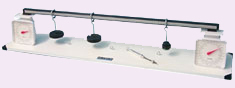
Forces on a Beam Apparatus
Features
- Low cost, effective teaching
- Self-contained
- Bench mounted
- Direct measurement of reactions by
scales
- Loads and supports can be placed in
any position
- Practical verification of equilibrium of
vertical force or moments
- Simply supported beams or levers
- Three year warranty
Range of Experiments
- Experimental determination of the reaction forces in the supports of a simply supported beam under various loadings
- Measurement of loads and moments on a lever
- Comparison with calculated results and validation of the principle of equilibrium
Description
A
horizontal length of material with a vertical load system is called a
beam. It is one of the most basic engineering ways of supporting a load.
External forces such as the applied loads and the beam support
reactions have to be in equilibrium. Given a loading system, the support
reactions can be calculated from force and moment equations.
This
apparatus is designed for simple experiments and demonstrations on
simply supported beams. Two scales act as supports and enable reactions
to be read directly. Two movable load hangers allow loads to be put in a
number of positions.
Levers can be investigated by placing the
beam across one of the scales. Different leverage ratios can be set up
using an adjustable tie rod which locates in one of three alternative
positions on the base plate. The force in the rod is measured by a
linear spring balance.
This equipment is part of a range designed
to both demonstrate and experimentally confirm basic engineering
principles. Great care has been given to each item so as to provide wide
experimental scope without unduly complicating or compromising the
design. Each piece of apparatus is self-contained and compact. Setting
up time is minimal, and all measurements are made with the simplest
possible instrumentation, so that the student involvement is purely with
the engineering principles being taught. A complete instruction manual
is provided describing the apparatus, its application, experimental
procedure and typical test results. |
 |
| |
|
| |
|
|
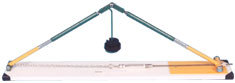
Triangle of Forces Apparatus
Features
- Low cost, effective teaching
- Self-contained
- Bench mounted
- Direct measurement of forces
- Adjustable lines of action of forces
- Practical verification of triangle of forces
- Three year warranty
Range of Experiments
- To find any suitable combination of three coplanar forces in equilibrium
- To compare the results with the graphical solution obtained by drawing the triangle of forces
- To demonstrate that th resultant of two known forces is equal and opposite to the equilibrant found experimentally
Description
A
bench mounted circular table with a central pin and 360º protractor has
three pulleys on adjustable clamps round the edge. Conditions of
equilibrium are obtained by centralising a small cord ring over the
central pin with cords to load hangers where the loads and lines of
action are variable.
The triangle of forces in equilibrium can be constructed and the resultant of two known forces can be found.
This
equipment is part of a range designed to both demonstrate and
experimentally confirm basic engineering principles. Great care has been
given to each item so as to provide wide experimental scope without
unduly complicating or compromising the design. Each piece of apparatus
is self-contained and compact. Setting up time is minimal, and all
measurements are made with the simplest possible instrumentation, so
that the student involvement is purely with the engineering principles
being taught. A complete instruction manual is provided describing the
apparatus, its application, experimental procedure and typical test
results. |
 |
|
|
|
|
