| Scientific Equipments & Products |
|
|
| Strength of Materials: |
| Strength of Materials Manufacturers - Deflection of Beams Apparatus, Torsion of Bars Apparatus, Advanced Beam Testing Apparatus, Extension of Wires Apparatus and Eccentrically Loaded Tie Apparatus |
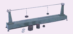
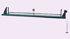
 Deflection of Beams Apparatus Deflection of Beams Apparatus
.Features
- Rigid base and supports
- Choice of end conditions
a) knife edge
b) built-in
- Beams or cantilevers
- Deflection and slope measurable
- Three year warranty
Range of Experiments
- Verification of beam deflection formula
- Deflection and slope of beams and cantilevers
- Verification of both area - moment theorems
Description
The
bench mounted apparatus has a heavy steel base with a fixed support at
one end and a moveable support at the other. The supports can be fitted
with knife edges or clamp plates one of which permits horizontal
movement for an encastre beam. A steel beam and two load hangers are
supplied together with two dial gauges for measuring beam deflections
and slopes.
This equipment is part of a range designed to both
demonstrate and experimentally confirm basic engineering principles.
Great care has been given to each item so as to provide wide
experimental scope without unduly complicating or compromising the
design. Each piece of apparatus is self-contained and compact. Setting
up time is minimal, and all measurements are made with the simplest
possible instrumentation, so that the student involvement is purely with
the engineering principles being taught. A complete instruction manual
is provided describing the apparatus, its application, experimental
procedure and typical test results. |
 |
| |
|
| |
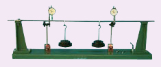
Deflection of Beams Apparatus
Features
- Rigid base and supports
- Choice of end conditions
a) knife edge
b) built-in
- Beams or cantilevers
- Deflection and slope measurable
- Three year warranty
Range of Experiments
- Verification of beam deflection formula
- Deflection and slope of beams and cantilevers
- Verification of both area - moment theorems
Description
The
bench mounted apparatus has a steel base with a fixed support at one
end and a moveable support at the other. The supports can be fitted with
knife edges or clamp plates. A steel beam and two load hangers are
supplied together with two dial gauges for measuring beam deflections
and slopes.
This equipment is part of a range designed to both
demonstrate and experimentally confirm basic engineering principles.
Great care has been given to each item so as to provide wide
experimental scope without unduly complicating or compromising the
design. Each piece of apparatus is self-contained and compact. Setting
up time is minimal, and all measurements are made with the simplest
possible instrumentation, so that the student involvement is purely with
the engineering principles being taught. A complete instruction manual
is provided describing the apparatus, its application, experimental
procedure and typical test results. |
 |
| |
|
| |
|
|
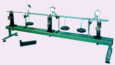
Advanced Beam Testing Apparatus
- Cost Effective Teaching
- Comprehensive theory of beams
- Simple and propped cantilevers
- Simply supported, fixed and continuous beams
- Three piers measure positive and
negative reactions
- Piers include a re-levelling system
- Three dial gauges on stands
- Point loads and distributed loading
- Six test beams to verify all variables
- Two optional extra sets of selected beams
- Data logging option
- Three year warranty
Range of Experiments
- All variables in deflection of beams
- Slope and curvature of beams
- Support reactions of single span and continuous beams
- Effect of sinking supports
- Area moment theorems
- Super-position
- Clerk Maxwell's reciprocal theorum
- Flitched beams
- Non-uniform beams
Description
The
apparatus provided allows an unlimited range of beam experiments to be
performed to measure support reactions and the deflections and rotations
of simply supported, fixed and two span continuous beams. The end clamp
also offers work on simple and propped cantilevers. In addition the
effect of sinking supports on a continuous beam can be studied.
The
experiments are assembled on a bench mounted twin beam base standing on
end frames with levelling feet. Three load measuring piers with a
digital read out in decaNewtons can be clamped to the base anywhere
within its length of 1.2 m. These piers are equipped with a height
correction system to compensate for the vertical deflection of the load
indicator and are fitted with beam connectors which provide pinned
conditions for both downward and upward beam reactions. A fourth pier is
a simple clamp for supporting a cantilever or the fixed end of a beam.
Three
dial gauges on stands can be clamped anywhere on the base. Four load
hangers provide for point loads, while a set of slotted weights can be
used to simulate a distributed load on a beam. The set of test beams
affords the study of all the variables in the standard formulae for
uniform beams.
This equipment is part of a range designed to both
demonstrate and experimentally confirm basic engineering principles.
Great care has been given to each item so as to provide wide
experimental scope without unduly complicating or compromising the
design. Each piece of apparatus is self-contained and compact. Setting
up time is minimal, and all measurements are made with the simplest
possible instrumentation, so that the student involvement is purely with
the engineering principles being taught. A complete instruction manual
is provided describing the apparatus, its application, experimental
procedure and typical test results.
|
 |
| |
|
| |
|
|
Torsion of Bars Apparatus
Features
- Low cost effective teaching
- Self-contained
- Bench-mounted
- Direct application of torque and measurement of angle of twist
- Determination of modulus of rigidity for different materials
- 3 year warranty
Range of Experiments
- To measure the angle of twist produced by torsional loads for various specimens and verify that the relationship is linear.
- To determine the modulus of rigidity for specimens of various materials
Description
Torsional
loads are common in power transmission shafts, and in certain cases can
also occur in structural members. It is thus very important that
engineers understand the relationship between the torsional load applied
to a particular beam and the angular twist produced. Also, engineers
must understand how this relationship varies with the material from
which the beam is made and its cross sectional polar moment of area.
This apparatus allows these relationships to be investigated directly.
Specimens
are rigidly held in a clamp fixed to one end of the base frame of the
apparatus. A short shaft mounted in the bearing has a three jaw chuck
facing the clamp and a torsion head at the outward side. The torsion
head and chuck are used to apply torsional loads to the specimen. A
rotation scale and pointer can be attached to any point on the
specimen's length to find the angle of twist of the specimen. Four
specimens are provided as standard, namely :
Mild steel rod 460 x 5mm dia.
Brass rod 460 x 5 mm dia.
Aluminium alloy rod 460 x 4.76mm dia.
Nylon rod 460 x 6.35mm dia.
This
equipment is part of a range designed to both demonstrate and
experimentally confirm basic engineering principles. Great care has been
given to each item so as to provide wide experimental scope without
unduly complicating or compromising the design. Each piece of apparatus
is self-contained and compact. Setting up time is minimal, and all
measurements are made with the simplest possible instrumentation, so
that the student involvement is purely with the engineering principles
being taught. A complete instruction manual is provided describing the
apparatus, its application, experimental procedure and typical test
results. |
 |
| |
|
| |
|
|
Eccentrically Loaded Tie Apparatus
Features
- Low cost, effective teaching
- Self-contained
- Bench-mounted
- Combined bending and tension
- Three eccentricities
- Three year warranty
Range of Experiments
- To measure the vertical bending deflection of the bar and to compare with theoretical predictions.
- To assess the effect of eccentricity of loading.
Description
Sometimes
in the design of a structure, a tension member has to be offset from
the line of action of the force. The member then has to carry combined
tension and bending loads, the latter increasing with the eccentricity
of the load. The eccentricity is exaggerated to make visual appreciation
of the phenomenon possible. When the load line is outside the middle
third of a square tie bar, as in this experiment, the bending moment
predominates and the bending deflection may be considerable.
The
apparatus enables both the load and eccentricity to be varied. A 9mm
square section by 800mm long specimen is provided, together with dial
gauge and load hanger. Different shaped specimens can be manufactured in
the college workshop as required.
This equipment is part of a
range designed to both demonstrate and experimentally confirm basic
engineering principles. Great care has been given to each item so as to
provide wide experimental scope without unduly complicating or
compromising the design. Each piece of apparatus is self-contained and
compact. Setting up time is minimal, and all measurements are made with
the simplest possible instrumentation, so that the student involvement
is purely with the engineering principles being taught. A complete
instruction manual is provided describing the apparatus, its
application, experimental procedure and typical test results. |
 |
| |
|
| |
|
|
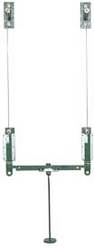
Extension of Wires Apparatus
Features
- Low cost effective teaching
- Self-contained
- Wall-mounted
- Simple determination of Young's modulus
- Verification of Hooke's Law
- Range of specimen material and thickness available
- 3 year warranty
Range of Experiments
- To determine Young's modulus of elasticity for the specimen wire
- To verify Hooke's Law
Description
Loaded
wires form a simple experiment which produces excellent and easy to
understand results. A single wire can be used to determine Young's
Modulus of Elasticity for the material, and to confirm Hooke's Law.
Two
brackets are secured to a wall minium 2m apart in a vertical line; a
top bracket from which to hang a specimen wire, and a slider bracket
used to measure the extension of the wire. The slider includes a vernier
for accurate measurement. For safety, the lower bracket should be
reasonably close to the ground.
This equipment is part of a range
designed to both demonstrate and experimentally confirm basic
engineering principles. Great care has been given to each item so as to
provide wide experimental scope without unduly complicating or
compromising the design. Each piece of apparatus is self-contained and
compact. Setting up time is minimal, and all measurements are made with
the simplest possible instrumentation, so that the student involvement
is purely with the engineering principles being taught. A complete
instruction manual is provided describing the apparatus, its
application, experimental procedure and typical test results. |
 |
| |
|
| |
|
|
Compound Wires Apparatus
Features
- Low cost effective teaching
- Self-contained
- Wall-mounted
- Simple determination of Young's modulus
- Verification of Hooke's Law
- Range of specimen material and thickness available
- Investigation of stresses in compound
suspension
- 3 year warranty
Range of Experiments
- To determine Young's modulus of elasticity for the specimen wire
- To verify Hooke's Law
- To evaluate the equivalent modulus of elasticity for the combined wire suspension
- To determine the load in the wire under conditions of equal strain in each wire.
- To compare experimental and theoretical results
Description
Loaded
wires form a simple experiment which produces excellent and easy to
understand results. A single wire can be used to determine Young's
Modulus of Elasticity for the material, and to confirm Hooke's Law. With
two wires, the experiment can be widened to investigate the effective
characteristics of two different materials subjected to a common strain.
Two
parallel sets of brackets are secured to a wall minium 2m apart in a
vertical line; a top bracket from which to hang a specimen wire, and a
slider bracket used to measure the extension of the wire. The slider
includes a vernier for accurate measurement. For safety, the lower
bracket should be reasonably close to the ground. The lower ends of each
slide are connected by a link. A load hanger can be moved along the
link until strains are equalised in each wire. The wires may be of
different materials, but must be the same length.
This equipment
is part of a range designed to both demonstrate and experimentally
confirm basic engineering principles. Great care has been given to each
item so as to provide wide experimental scope without unduly
complicating or compromising the design. Each piece of apparatus is
self-contained and compact. Setting up time is minimal, and all
measurements are made with the simplest possible instrumentation, so
that the student involvement is purely with the engineering principles
being taught. A complete instruction manual is provided describing the
apparatus, its application, experimental procedure and typical test
results. |
 |
| |
|
| |
|
|
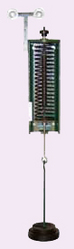
Extension of Springs Apparatus
Features
- Low cost effective teaching
- Self-contained
- Wall-mounted
- Demonstrates Hooke's Law
- Measurement of spring stiffness
- 3 year warranty
Range of Experiments
- To test the relationship between the load applied and the change in length of a spring (Hooke's Law)
- To determine spring stiffness
- For
more advanced courses, the dependence of spring stiffness on the wire
diameter, spring diameter, length, number of turns and material.
Comparison with theoretical estimate.
Description
Springs
are used in engineering to store energy or to provide restoring forces.
Both compression and tension springs may be encountered. The deflection
of a spring depends on the load applied to it, an observation enshrined
in Hooke's Law. Applications of springs are found in spring balances
which indicate loads by measuring spring deflections and in car
suspensions where they absorb energy caused by wheel vertical movement
due to potholes and bumps.
The equipment is designed to be fitted
to a wall. It is used to test tension springs up to 200mm in length.
The maximum spring diameter is 38mm.
A weight hanger is used to
apply a load to the spring. Spring deflection is measured with a sliding
scale which can be easily re-zeroed to suit the length of the spring. A
spring, weight hanger and weights are supplied with each piece of
equipment.
This equipment is part of a range designed to both
demonstrate and experimentally confirm basic engineering principles.
Great care has been given to each item so as to provide wide
experimental scope without unduly complicating or compromising the
design. Each piece of apparatus is self-contained and compact. Setting
up time is minimal, and all measurements are made with the simplest
possible instrumentation, so that the student involvement is purely with
the engineering principles being taught. A complete instruction manual
is provided describing the apparatus, its application, experimental
procedure and typical test results. |
 |
| |
|
| |
|
|
Compression of Springs Apparatus
Features
- Low cost effective teaching
- Self-contained
- Wall-mounted
- Demonstrates Hooke's Law
- Measurement of spring stiffness
- 3 year warranty
Range of Experiments
- To test the relationship between the load applied and the change in length of a spring (Hooke's Law)
- To determine spring stiffness
- For
more advanced courses, the dependence of spring stiffness on the wire
diameter, spring diameter, length, number of turns and material.
Comparison with theoretical estimate.
Description
Springs
are used in engineering to store energy or to provide restoring forces.
Both compression and tension springs may be encountered. The deflection
of a spring depends on the load applied to it, an observation enshrined
in Hooke's Law. Applications of springs are found in spring balances
which indicate loads by measuring spring deflections and in car
suspensions where they absorb energy caused by wheel vertical movement
due to potholes and bumps.
The equipment is designed to be fitted
to a wall. It can use compression springs up to 150mm long. The maximum
spring diameter is 38mm.
A weight hanger is used to apply a load
to the spring. Spring deflection is measured with a sliding scale which
can be easily re-zeroed to suit the length of the spring. A spring,
weight hanger and weights are supplied with each piece of equipment.
This
equipment is part of a range designed to both demonstrate and
experimentally confirm basic engineering principles. Great care has been
given to each item so as to provide wide experimental scope without
unduly complicating or compromising the design. Each piece of apparatus
is self-contained and compact. Setting up time is minimal, and all
measurements are made with the simplest possible instrumentation, so
that the student involvement is purely with the engineering principles
being taught. A complete instruction manual is provided describing the
apparatus, its application, experimental procedure and typical test
results. |
 |
| |
|
| |
|
|
Internal Elastic Forces Apparatus
Features
- Low cost effective teaching
- Self-contained
- Wall-mounted
- Simulates strains for a bolt stressing
a tube
- Determination of stiffness of tension and compression springs
- 3 year warranty
Range of Experiments
- To determine the stiffness of springs in tension and compression
- To
investigate a self-straining system similar to a bolt in a tube. In
particular to measure the reduction in length of the "tube", and the
forces in the springs
- To measure the increase in length and forces in the system due to applying an external tensile load
Description
The
apparatus is a self straining system analogous to a bolt stressing a
tube, enabling the final overall deflection of the system to be
determined. It consists of a frame in which there are two springs. A
tension spring with means of adjusting its length has a disc at its
lower end. Between this disc and the top of the frame is fitted a
compression spring. A weight hanger attached to the disc enables the two
springs to be loaded. The stiffness of the two springs is different so
that an overall deflection is induced.
The two springs can be
installed separately in the frame so that the stiffness of each can be
determined. In the case of the compression spring, it is necessary to
apply loads through a cord and pulley arrangement. A graduated scale
alongside the disc shows the deflection of the spring(s). Excellent
results are achieved due to the low friction of the equipment.
This
equipment is part of a range designed to both demonstrate and
experimentally confirm basic engineering principles. Great care has been
given to each item so as to provide wide experimental scope without
unduly complicating or compromising the design. Each piece of apparatus
is self-contained and compact. Setting up time is minimal, and all
measurements are made with the simplest possible instrumentation, so
that the student involvement is purely with the engineering principles
being taught. A complete instruction manual is provided describing the
apparatus, its application, experimental procedure and typical test
results. |
 |
| |
|
| |
|
|
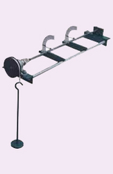
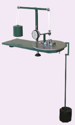
Deflection of Curved Bars Apparatus
Features
- Universal machine
- Compact, bench mounted
- Four specimens supplied: Circular ring,
Semi-circle, Quadrant and Davit
- Measurement of oscillation frequency
- Measurement of horizontal and vertical deflections by dial gauges
- Demonstrates strain energy concepts
- Three year warranty
Range of Experiments
- To
experimentally determine the vertical and horizontal deflections of
various curved bars whose cross sectional dimensions are small compared
with the bar radius.
- To compare with theoretical estimates using strain energy theories such as Castigliano's first theorem.
Description
The
theoretical deflections of curved shapes are most easily found by
applying strain energy ideas, such as Castigliano's first theorem. The
shapes chosen provide a relatively easy introduction to the use of such
techniques, which students often seem to find difficult to grasp.
A
bench mounted base supports a curved bar formed into a ring,
semi-circle or quadrant/davit. Loads are applied by specially designed
weight hangers so that the specimen bends. Horizontal and vertical
deflections are measured by dial gauges rigidly attached to the base.
The bars can be readily changed and the position of the dial gauges
relocated to measure the deflections of the new configuration. Bars,
weight hangers and a set of weights are supplied.
This equipment
is part of a range designed to both demonstrate and experimentally
confirm basic engineering principles. Great care has been given to each
item so as to provide wide experimental scope without unduly
complicating or compromising the design. Each piece of apparatus is
self-contained and compact. Setting up time is minimal, and all
measurements are made with the simplest possible instrumentation, so
that the student involvement is purely with the engineering principles
being taught.
A complete instruction manual is provided
describing the apparatus, its application, experimental procedure and
typical test results. |
 |
| |
|
| |
|
|
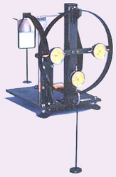
Combined Bending and Torsion Apparatus
Features
- Low cost effective teaching
- Self-contained
- Bench-mounted
- Range of specimen materials
- Introduction to theories of failure
- Bending and torsional loading ratios
variable
- 3 year warranty
Range of Experiments
- To determine elastic failure of a specimen subjected to several ratios of bending and torsion simultaneously
- To compare the results with the established theories of failure
Description
Much
of the design of parts in mechanical and civil engineering is
complicated by there being biaxial or triaxial stresses for which some
failure state has to be determined. Obvious examples are high pressure
cylinders containing liquids or gases and concrete hinges for large
bridge bearings. For more than a century, physicists, mathematicians and
engineers have been proposing various theories of failure. Some
theories have been attempts to explain observed failures while a few
have tried to base a mechanism on fundamental properties of materials.
It
is evident that there is a considerable difference between the
behaviour of ductile and brittle materials. That apart, it is quite
difficult to determine failure with sufficient accuracy in experiments
designed to show which failure theory is most applicable. Hence, it is
frequently found that codes of practice lay down what appears to be a
somewhat empirical design method which experience has proved to be
workable.
This simple machine uses inexpensive test specimens
made from round bar. The specimen is clamped at one end to the base
bracket and at the other to a counterbalanced circular loading plate.
This plate is graduated in 15° intervals. A special hanger enables pure
bending, pure torque or combined loads to be applied depending on the
position of the plate. The specimen deflection is measured by a dial
gauge mounted diametrically opposite the load point. In the event of a
specimen failure safety is ensured by set screws
This equipment
is part of a range designed to both demonstrate and experimentally
confirm basic engineering principles. Great care has been given to each
item so as to provide wide experimental scope without unduly
complicating or compromising the design. Each piece of apparatus is
self-contained and compact. Setting up time is minimal, and all
measurements are made with the simplest possible instrumentation, so
that the student involvement is purely with the engineering principles
being taught. A complete instruction manual is provided describing the
apparatus, its application, experimental procedure and typical test
results. |
 |
| |
|
| |
|
|
Critical Load on Struts Apparatus
Features
- Low cost effective teaching
- Self-contained
- Wall-mounted
- Seven mild steel struts supplied
- Extra strut available, eccentrically loaded
- Tests pivoted or built-in ends
- Longitudinal and lateral loading
- Comparison with theoretical predictions
- 3 year warranty
Range of Experiments
- Determination of Young's modulus of Elasticity for specimen material
- Struts with pivoted ends, but varying lengths
a) to assess the effect of slenderness ratio on crippling load for the same specimen material
b) to compare with Euler and Perry-Robertson formulae predictions
- Struts of same length, but different end fixings
a) to assess the effect of end constraint on crippling load
b) to compare with Euler and Perry-Robertson formulae predictions
c) to observe the shape of each critically loaded strut
- Slender strut with eccentric loading (optional accessory)
a)
to investigate how the lateral deflection of an eccentrically loaded
strut varies with the applied load and eccentricity and to produce a
Southwell plot.
b) to compare the experimental and theoretical values for maximum lateral deflection
Description
This
equipment is part of a range designed to both demonstrate and
experimentally confirm basic engineering principles. Great care has been
given to each item so as to provide wide experimental scope without
unduly complicating or compromising the design. Each piece of apparatus
is self-contained and compact. Setting up time is minimal, all
measurements are made with the simplest possible instrumentation, so
that the student involvement is purely with the engineering principles
being taught.
A piece of material in compression is called a
strut. If it is short and stubby it will fail by compressive stress, but
if it is slender the failure mode is that of buckling. The load at
which the strut buckles depends on the way in which the ends are
restrained. Built-in ends resist buckling more than ends which are free
to move. The apparatus shows how the buckling mechanism occurs, and the
influence of the end restraint.
The apparatus is rigid and wall
mounted. It can test struts between 0.75 m and 1 m in length with either
pivoted or built-in ends. Axial load is applied to a load hanger linked
by cables to the yoked ram whose travel can be pre-set to prevent
permanent damage to the strut. A lateral load can be applied at any
position to the strut. Seven mild steel specimens are supplied as
standard. A dial gauge is supplied to measure strut deflection.
With
this equipment, an in depth study can be made of the factors that
effect the buckling of a strut; its length, cross section, material and
end restraint.
Young's modulus for the strut material is derived
in a secondary experiment, using the same equipment but with a specimen
loaded as a beam.
This equipment is part of a range designed to
both demonstrate and experimentally confirm basic engineering
principles. Great care has been given to each item so as to provide wide
experimental scope without unduly complicating or compromising the
design. Each piece of apparatus is self-contained and compact. Setting
up time is minimal, and all measurements are made with the simplest
possible instrumentation, so that the student involvement is purely with
the engineering principles being taught. A complete instruction manual
is provided describing the apparatus, its application, experimental
procedure and typical test results. |
 |
| |
|
| |
|
|
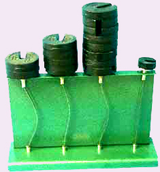
Critical Condition of Struts
Features
- Low cost, effective teaching
- Self-contained
- Bench-mounted
- Demonstration of shape of a deflected
strut
- Direct loading gives highly visual impact
of Euler theory
- All possible end constraints
- Comparison with theoretical predictions
- Three year warranty
Range of Experiments
- To observe the behaviour of four struts of the same length but with different end constraints when subjected to buckling loads.
- To compare the result with theoretical predictions, such as Euler's formula.
Description
A
piece of material in compression is called a strut. If it is short and
stubby it will fail by compressive stress, but if it is slender the
failure mode is that of buckling. The load at which the strut buckles
depends on the way in which the ends are restrained. Built-in ends
resist buckling more than ends which are free to move. The apparatus
shows how the buckling mechanism occurs, and the influence of the end
restraint.
The apparatus comprises a sheet metal frame which
supports four slender spring steel struts having loading platforms at
their top ends. Each strut has a different end constraint so that
comparisons can be instantly made in a highly visible way.
a) Both ends pinned
b) One end pinned, the other end fixed
c) Both ends fixed
d) Base fixed, top free
For
the first three, the ends move inwards as the strut buckles. The
loading platforms act through relatively friction free guide bushes.
This
equipment is part of a range designed to both demonstrate and
experimentally confirm basic engineering principles. Great care has been
given to each item so as to provide wide experimental scope without
unduly complicating or compromising the design. Each piece of apparatus
is self-contained and compact. Setting up time is minimal, and all
measurements are made with the simplest possible instrumentation, so
that the student involvement is purely with the engineering principles
being taught. A complete instruction manual is provided describing the
apparatus, its application, experimental procedure and typical test
results. |
 |
| |
|
| |
|
|
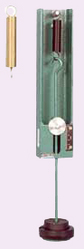
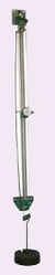
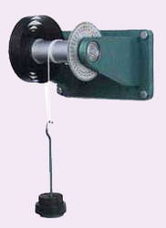
Torsion of a Spiral Spring
Features
- Low cost, effective teaching
- Self-contained
- Wall-mounted
- Measurement of torsional stiffness
- Demonstration of Hooke's law for
torsional spring
- Comparison with theoretical predictions
- Three year warranty
Range of Experiments
- To compare the experimental stiffness of a plane spiral spring with theoretical predictions.
- To observe if the spring exhibits a linear elastic behavior.
Description
Spiral
springs are used to provide a resisting or restoring torque to a shaft
when it is rotated through an angular dispacement. They exhibit similar
stiffness characteristics to linear springs, except that the effect is
one of torque rather than force. The stiffness of a spiral spring
depends on its physical dimensions and the rigidity of the steel strip
from which it is formed. The student can easily calculate the
theoretical stiffness of the spring, and compare the value with simple
experimental results.
The wall mounted unit consists of a spiral
spring coiled from a length of 25 x 0.6mm steel strip to give an
effective length of 2 metres, attached to a shaft mounted in ball
bearings. A cord carrying a weight hanger is wound round the shaft, and a
load applied to twist the spring. Spring deflection is measured with an
attached 360° scale. A cord and weight hanger are supplied.
This
equipment is part of a range designed to both demonstrate and
experimentally confirm basic engineering principles. Great care has been
given to each item so as to provide wide experimental scope without
unduly complicating or compromising the design. Each piece of apparatus
is self-contained and compact. Setting up time is minimal, and all
measurements are made with the simplest possible instrumentation, so
that the student involvement is purely with the engineering principles
being taught. A complete instruction manual is provided describing the
apparatus, its application, experimental procedure and typical test
results. |
 |
| |
|
| |
|
|
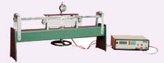
Calibration of Electrical Resistance Strain Gauges
Features
- Cost, effective
- Self-contained
- Calibration of strain gauges to
- Determination of gauge factor
- Introduction to calibration and standards
- Introduction to probability of production
errors of batch made strain gauges
- Three year warranty
Range of Experiments
- To study the application of structural theory in strain gauge calibration
- To asses the accuracy of calibration techniques
- To introduce the application of probability theory in production quality control
Description
Based
on BSI Draft for development 6:1972 this gauge factor test rig is a
precision item specially designed for measuring the gauge factor of an
electrical resistance strain gauge. It also demonstrates how structural
theory is used to determine the strain on the surface of a test bar for
calibration purposes.
The apparatus is based on a four point
loading system which produces circular bending in the centre section of a
precision ground steel beam. A device for measuring the curvature over a
length of 300mm has been calibrated to give direct readings of strain
up to 1000 microstain.
For demonstration purposes a pair of
electrical resistance gauges have been bonded to the beam, but for
calibration work users will bond their own gauges in accordance with
DD6/1972.
An extension from the normal technical experiment is to
introduce students to probability theory to assess likely differences
in gauge factor due to batch manufacture.
This equipment is part
of a range designed to both demonstrate and experimentally confirm basic
engineering principles. Great care has been given to each item so as to
provide wide experimental scope without unduly complicating or
compromising the design. Each piece of apparatus is self-contained and
compact. Setting up time is minimal, and all measurements are made with
the simplest possible instrumentation, so that the student involvement
is purely with the engineering principles being taught. A complete
instruction manual is provided describing the apparatus, its
application, experimental procedure and typical test results. |
 |
| |
|
| |
|
|
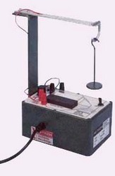
Electrical Resistance Strain Gauge
Features
- Low cost effective teaching
- Bench mounted
- Self contained
- Wheatstone bridge and temperature compensation dummy gauge included
- Introduction to strain gauges
- Bending and Torsion included
- Optional extras for Tension and
Compression
- Three year warranty
Range of Experiments
- To show the application of strain gauges in the measurement of stress, due to bending and torsion
- To demonstrate the use of a Wheatstone Bridge in measuring change of resistance.
- With
the optional extras to show other methods of temperature compensation
in conjunction with tension and compression specimens.
Description
The
apparatus has been designed to illustrate the basic features of
electrical resistance strain gauges and their application to measurement
of strain and the derivation of stress levels, in bending, torsion,
tension and compression.
An alloy cantilever has a single gauge
bonded onto its surface, and an identical gauge is fixed to an
unstressed piece of the same material for temperature compensation. The
two gauges form part of a Wheatstone Bridge which has an apex or
balancing potentiometer, and whose meter is calibrated directly in
microstrains. The cantilever is loaded by weights hung from its free
end, a weight hanger is included.
To extend the scope of the
apparatus the cantilever can be replaced by a torsion bar having two
gauges bonded orthogonally at 45º
For a complete study of strain
gauging two optional extra accessories demonstrate averaging techniques
for tension and compression specimens.
This equipment is part of a
range designed to both demonstrate and experimentally confirm basic
engineering principles. Great care has been given to each item so as to
provide wide experimental scope without unduly complicating or
compromising the design. Each piece of apparatus is self-contained and
compact. Setting up time is minimal, and all measurements are made with
the simplest possible instrumentation, so that the student involvement
is purely with the engineering principles being taught.
A
complete instruction manual is provided describing the apparatus, its
application, experimental procedure and typical test results. |
 |
| |
|
| |
|
|
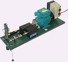
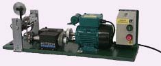
Rotating Fatigue Machine Mk3
Features
- Self contained
- Bench mounted
- Fully guarded
- Digital readout of revolutions to failure
- Motor stops when specimen fails
- Necked specimens, steel, aluminium alloy
and brass
- Ideal introduction to fatigue
- Optional extra for alternating bending
fatigue
- Three year warranty
Range of Experiments
- To
make an introductory study of fatigue using a Wohler rotating fatigue
apparatus, including the time to failure caused by various stress levels
and materials
- The accessory, HSM19X affords bending fatigue of
a cantilevered strip of metal or plastic in modes varying from
alternating to fluctuating stresses
Description
This
machine has been designed to introduce students to the effects of
fatigue. A simple cantilever specimen rotates at about 5700 or 1425
revs/min, inducing a sinusoidal variation of bending stress. At the
faster speed, a third of a million stress reversals occur each hour, so
failure should occur within a day. Failure can be hastened by using a
specimen with a stress raiser.
The loading system cancels its own
self weight enabling any desired value of bending stress to be applied,
ten mild steel specimens are supplied. Axiality has been ensured, and
care has been taken to reduce the effects of vibration. When failure
occurs, a microswitch stops the motor and the cycles to failure are
registered on a 5 digit revolution counter.
All rotating parts
are shielded and a safety guard is provided to restrain the broken
specimen. The apparatus is mounted on a heavy steel base plate and is
designed to overhang the bench or pedestal on which it is placed.
Ideally a heavy pedestal (eg concrete), isolated from the floor by
rubber matting, should be used to minimise shock loads.
An additional accessory for alternating bending fatigue and additional specimens are available.
This
equipment is part of a range designed to both demonstrate and
experimentally confirm basic engineering principles. Great care has been
given to each item so as to provide wide experimental scope without
unduly complicating or compromising the design. Each piece of apparatus
is self-contained and compact. Setting up time is minimal, and all
measurements are made with the simplest possible instrumentation, so
that the student involvement is purely with the engineering principles
being taught. A complete instruction manual is provided describing the
apparatus, its application, experimental procedure and typical test
results. |
 |
| |
|
| |
|
|
Alternating Bending Fatigue Machine
Features
- Self-contained
- Bench-mounted
- Fully guarded
- Digital readout of revolutions to failure
- Determination of gauge factor
- Motor stops when specimen fails
- Specimens from strips of plastics or metals
- Special setting details supplied
- Optional extra for rotating fatigue
- Three year warranty
Range of Experiments
- Bending fatigue of a cantilevered strip of metal or plastic in modes varying from alternating to fluctuating stresses
- The
accessory HSM20X allows an introductory study of fatigue using a Wohler
rotating fatigue test, including time to failure caused by various
stress levels and materials
Description
To extend the range
of fatigue testing to strips of plastic or metal, this variant of the
popular rotating fatigue machine HSM19 has been developed. Using the
drive mechanism and base plate of the new HSM19 Mk.3 with a heavy steel
portal straddling the width of the base an alternating displacement can
be imposed on the free end of a cantilever. The frequency of the
reciprocating force is around 24Hz for plastics or 100Hz for metals.
A
rotating faceplate carries an adjustable eccentric bearing driving a
connecting rod attached to the cantilever. The bridge to which this test
piece is clamped can be adjusted vertically so that the imposed
displacement can be varied. A counter with a 50:1 reduction gear is
driven by the electric motor, offering a 1:100 or 1:25 count depending
on the drive ratio to the faceplate. Microswitches detect failure of the
specimen and stop the motor.
To test a specimen a special dial
gauge enables a calculated deflection to be set for the actual maximum
bending stress of the specimen. An instruction manual containig a set of
nomograms is provided to assist the user.
Great care has been
taken to minimise extraneous vibration. All moving parts are shielded
within a protective cover which can be removed during setting up. A
guard surrounds the connecting rod to prevent damage when the specimen
breaks.
It is possible to add extra parts (HSM20X) to this
machine so that the rotating fatigue test can be carried out as an
alternative.
This equipment is part of a range designed to both
demonstrate and experimentally confirm basic engineering principles.
Great care has been given to each item so as to provide wide
experimental scope without unduly complicating or compromising the
design. Each piece of apparatus is self-contained and compact. Setting
up time is minimal, and all measurements are made with the simplest
possible instrumentation, so that the student involvement is purely with
the engineering principles being taught. A complete instruction manual
is provided describing the apparatus, its application, experimental
procedure and typical test results. |
 |
|
|
|
|
